
Purpose
This article describes the procedure to enable LACP / 802.3ad, vLANs and Jumbo Frames on Cohesity cluster.
Assumptions
- This is a green-field deployment document, not a conversion.
- The Cohesity unit has already completed the cluster setup and has allocated and assigned IPs for IPMI, Node and VIP interfaces.
- No vlans are configured on the Cohesity cluster.
- Cisco Nexus ports are configured as access ports on the storage management vlan
- Cisco Nexus 93180 Switching is in place and VPCs are established.
- Management is on a separate switch.
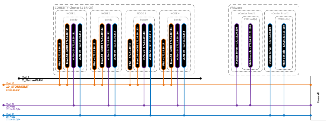
- Storage Management vLAN = 10
- Production 1 vLAN = 20
- Production 2 vLAN = 30
- IPMI has interfaces are established on your storage management network.
Disclaimer
I am not responsible if YOU blow up YOUR systems. Do your homework.
Diagrams
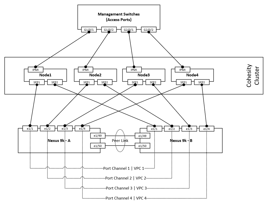
Node cabling guide
vLANs and Subnets
Procedure Overview
Order of Operations
Items 3-8 in the below list must be repeated for each node in the cluster.
- Configure Required vLANs on Cisco Nexus switches
- Configure interface descriptions on Cisco Nexus interfaces
- Configure Cisco Nexus switches for LACP
- Configure Cohesity Node(s) for LACP
- Configure Cisco Nexus switches for Jumbo Frames
- Configure Cohesity Node(s) for Jumbo Frames
- Configure Cisco Nexus switches for vLANs
- Configure Cohesity Node(s) for vLANs
Initial switch configurations
Configure vLANs on switch A & B
Config t
!
vlan 10
 name 10_STORMGMT
vlan 20
 name 20_Prod1
vlan 30
 name 30_Prod2
!
copy run st
Configure Port descriptions
Switch A
Config t
!
interface Ethernet1/1
description Cohesity-N1-P0
!
interface Ethernet1/2
description Cohesity-N2-P0
!
interface Ethernet1/3
description Cohesity-N3-P0
!
interface Ethernet1/3
description Cohesity-N3-P0
!
copy run st
Switch B
Config t
!
interface Ethernet1/1
description Cohesity-N1-P1
!
interface Ethernet1/2
description Cohesity-N2-P1
!
interface Ethernet1/3
description Cohesity-N3-P1
!
interface Ethernet1/3
description Cohesity-N3-P1
!
copy run st
Node 1
LACP
Cisco LACP Configuration
This is a 2 step processes. First, we must configure the port channel interfaces then we must add the member interfaces to the port-channel interface.
Switch A & B
Config t
!
interface port-channel1
description Cohesity-N1
switchport mode access
switchport access vlan 10
!
copy run st
Switch A & B
Config t
!
interface Ethernet1/1
channel-group 1 mode active
!
interface port-channel1
vpc 1
!
copy run st
Cohesity LACP Configuration
To enable LACP / 802.3ad on the cluster, the bond mode should be changed on the cluster and changes should be made on the switch to ensure network connectivity on the nodes. If LACP needs to be enabled for the entire cluster, the procedure should be followed on all the nodes, one node at a time to avoid any cluster service disruption. The following is the procedure to enable LACP.
- Login to the cluster node using SSH. For login credentials, please contact Cohesity Support.
- Edit bond0 interface and set the bond mode to 4.
sudo vi /etc/sysconfig/network-scripts/ifcfg-bond0
Change the “BONDING_OPTS” line and change the mode to 4 and save the file.
BONDING_OPTS="mode=4 miimon=100"
- Enable LACP/LAG configuration from the switch
- Restart the network on the node to enable LACP of the Cohesity node. Please ignore any Node down alert generated.
sudo systemctl restart network
- Run the following iris_cli command to set the new bonding mode in the cluster configuration.
iris_cli cluster -username= -password= edit-bm bonding-mode=4
- Check and confirm that the bond mode has changed on the nodes. Ensure that the bonding mode is set to “802.3ad 4”
[cohesity@cohesity-sre01-node-1 ~]$ cat /sys/class/net/bond0/bonding/mode 802.3ad 4
- Restart nexus and nexus_proxy services to ensure that the VIPs are up.
sudo systemctl stop nexus
nexus_proxy.sh stop
sudo systemctl start nexus
nexus_proxy.sh start
Verify LACP Configuration
Cisco
Run the show vpc command to validate the output, if further
sudo systemctl stop nexus
9k-sw01# sh vpc 1
vPC status
—————————————————————————-
Id Port Status Consistency Reason Active vlans
— ———— —— ———– —— —————
1 Po1 up success success 1,10,20,30
Please check “show vpc consistency-parameters vpc ” for the
consistency reason of down vpc and for type-2 consistency reasons forany vpc.
9k-sw01# show port-channel summary interface port-channel 1
Flags: D – Down P – Up in port-channel (members)
I – Individual H – Hot-standby (LACP only)
s – Suspended r – Module-removed
b – BFD Session Wait
S – Switched R – Routed
U – Up (port-channel)
p – Up in delay-lacp mode (member)
M – Not in use. Min-links not met
——————————————————————————–
Group Port- Type Protocol Member Ports
Channel
——————————————————————————–
1 Po1(SU) Eth LACP Eth1/1(P)
Cohesity
Confirm that LACP configuration is successful by browsing to that node with the Node IP.
Jumbo Frames
Cisco Jumbo Frames Configuration
Switch A & B
Config t
!
interface port-channel1
mtu 9216
!
copy run st
Cohesity Jumbo Frames Configuration
To enable Jumbo Frames, first ensure that the switch ports have the MTU set to 9000 and every network hop between those hosts and the Cohesity cluster also have the MTU set to 9000. Once the MTU has been set on the path between all hosts and the Cohesity cluster, log into each node and manually set the MTU size to 9000 on each of the network interfaces involved. The following procedure ca be used to change MTU on the cluster nodes.
- Edit the bond0 configuration and set “MTU=9000”
sudo vi /etc/sysconfig/network-scripts/ifcfg-bond0
The ifcfg-bond0 config file should have the MTU set to 9000.
DEVICE=bond0
USERCTL=no
BOOTPROTO=none
ONBOOT=yes
IPADDR=172.16.10.111
PREFIX=24
GATEWAY=172.16.10.1
MTU=9000
BONDING_OPTS="mode=4 miimon=100"
- Update the cluster config and set the new MTU size. The following iris_cli command can be used.
iris_cli -username= -password= cluster update mtu=9000
Example:
iris_cli -username=cohesity -password=CohesityPassw0rd cluster update mtu=9000
- Restart nexus proxy to ensure that the VIPs MTU settings are changed. restarting nexus_proxy reinitialized the VIPs.
allssh.sh “nexus_proxy.sh stop && nexus_proxy.sh start”
Verify Jumbo Frames Configuration
Cisco
9k-sw01# sh int po1 | inc MTU
The output of the show interface command should show MTU of 9216
MTU 9216 bytes, BW 10000000 Kbit, DLY 10 usec
Cohesity
netstat -ian
The output of the netstat command should show MTU of 9000 for all bond0* interfaces.
Iface      MTU    RX-OK RX-ERR RX-DRP RX-OVR    TX-OK TX-ERR TX-DRP TX-OVR Flg
bond0     9000 726974917      0 620460 0      3353577236      0      0      0 BMmRU
bond0:3   9000      - no statistics available -                        BMmRU
bond0:av  9000      - no statistics available -                        BMmRU
enp7s0f0  1500        0      0      0 0             0      0      0      0 BMU
enp7s0f1  1500        0      0      0 0             0      0      0      0 BMU
ens802f0  1500 726400981      0   5784 0      3353577233      0      0      0 BMsRU
ens802f1  1500   573938      0 573938 0             3      0      0      0 BMsRU
lo       65536 102513458      0      0 0      102513458      0      0      0 LRU
vLANs
NOTEs:
- With Cisco Nexus Port-Channels you should always add the interface to the port-channel with only the description configured. All Switchport and MTU details should be added to the port-channel interfaces and the member interfaces will inherit the configuration. Cisco Nexus 9000 Series NX-OS Interfaces Configuration Guide, Release 7.x
- (I have not been able to confirm this) Cohesity uses the Native vlan for cluster communications and this is the reason I have set the native vlan on the port-channel interfaces. Network security best practices state you should not allow any traffic over vlan 1. Most switch vendors use the “Default vlan” of 1.
Cisco vLAN Configuration
Switch A and B
Config t
!
interface port-channel1
switchport mode trunk
switchport trunk allowed vlan 10,20,30
Switchport trunk native vlan 2
!
copy run st
Cohesity vLAN Configuration
Cohesity did not document the fact that you need to configure the first vlan interface on the node. This is needed to be able to access the user interface post network port vlan trunk conversion. The fact that they added vlan management to the user interface in 5.x is much simpler to add “Additional” vlans however the NODE ip vlan interface still needs to be done first from the shell. I’ve also noticed that vlans configured from the user interface are dynamically build and taken down on cluster starts and stops. I’m more comfortable having the NODE interface vlan statically configured as I know it will be active always regardless of other operations.
First, we must manually configure the node interface vlan on bond0
This is done by copying the existing bond0 config file
Copy config file
Cd /etc/sysconfig/network-scripts/
Sudo cp ifcfg-bond0 ifcfg-bond0.10
Now update the config files according
Bond0 need to have all IP related info as it is no longer needed. The only remaining information is the interface bonding detail and MTU (NOTE: MTU must match on all the interfaces including the vlan interfaces)
Update bond0
Sudo vi ifcfg-bond0

DEVICE=bond0
USERCTL=no
BOOTPROTO=none
ONBOOT=yes
IPADDR=172.16.10.111
PREFIX=24
GATEWAY=172.16.10.1
MTU=9000
BONDING_OPTS="mode=4 miimon=100"
This should be the final file contents:
DEVICE=bond0
USERCTL=no
BOOTPROTO=none
ONBOOT=yes
IPADDR=172.16.10.111
PREFIX=24
GATEWAY=172.16.10.1
MTU=9000
BONDING_OPTS="mode=4 miimon=100"
Update bond0.10
Here we need to make some changes info to identify it as a vlan interface. First, we need to rename the device field and append the .10 (or vlan ID) to it. Next, we need to add the following fields: VLAN=yes, TYPE=Ethernet and lastly remove the bonding options “BONDING_OPTS”
Sudo vi ifcfg-bond0.10
DEVICE=bond0.10 USERCTL=no BOOTPROTO=none ONBOOT=yes VLAN=yes TYPE=Ethernet IPADDR=172.16.10.111 PREFIX=24 GATEWAY=172.16.10.1 MTU=9000BONDING_OPTS="mode=4 miimon=100"
This should be the final file contents
DEVICE=bond0.10 USERCTL=no BOOTPROTO=none ONBOOT=yes VLAN=yes TYPE=Ethernet IPADDR=172.16.10.111 PREFIX=24 GATEWAY=172.16.10.1 MTU=9000
Node 2
LACP
Cisco LACP Configuration
This is a 2 step processes. First, we must configure the port channel interfaces then we must add the member interfaces to the port-channel interface.
Switch A & B
Config t
!
interface port-channel2
description Cohesity-N2
switchport mode access
switchport access vlan 10
!
copy run st
Switch A & B
Config t
!
interface Ethernet1/2
channel-group 2 mode active
!
interface port-channel2
vpc 2
!
copy run st
Cohesity LACP Configuration
To enable LACP / 802.3ad on the cluster, the bond mode should be changed on the cluster and changes should be made on the switch to ensure network connectivity on the nodes. If LACP needs to be enabled for the entire cluster, the procedure should be followed on all the nodes, one node at a time to avoid any cluster service disruption. The following is the procedure to enable LACP.
- Login to the cluster node using SSH. For login credentials, please contact Cohesity Support.
- Edit bond0 interface and set the bond mode to 4.
sudo vi /etc/sysconfig/network-scripts/ifcfg-bond0
Change the “BONDING_OPTS” line and change the mode to 4 and save the file.
BONDING_OPTS="mode=4 miimon=100"
- Enable LACP/LAG configuration from the switch
- Restart the network on the node to enable LACP of the Cohesity node. Please ignore any Node down alert generated.
sudo systemctl restart network
- Run the following iris_cli command to set the new bonding mode in the cluster configuration.
iris_cli cluster -username= -password= edit-bm bonding-mode=4
- Check and confirm that the bond mode has changed on the nodes. Ensure that the bonding mode is set to “802.3ad 4”
[cohesity@cohesity-sre01-node-2 ~]$ cat /sys/class/net/bond0/bonding/mode 802.3ad 4
- Restart nexus and nexus_proxy services to ensure that the VIPs are up.
sudo systemctl stop nexus
nexus_proxy.sh stop
sudo systemctl start nexus
nexus_proxy.sh start
Verify LACP Configuration
Cisco
Run the show vpc command to validate the output, if further
9k-sw01# sh vpc 2
vPC status
—————————————————————————-
Id Port Status Consistency Reason Active vlans
— ———— —— ———– —— —————
2 Po2 up success success 1,10,20,30Please check “show vpc consistency-parameters vpc ” for the
consistency reason of down vpc and for type-2 consistency reasons forany vpc.9k-sw01# show port-channel summary interface port-channel 2
Flags: D – Down P – Up in port-channel (members)
I – Individual H – Hot-standby (LACP only)
s – Suspended r – Module-removed
b – BFD Session Wait
S – Switched R – Routed
U – Up (port-channel)
p – Up in delay-lacp mode (member)
M – Not in use. Min-links not met——————————————————————————–
Group Port- Type Protocol Member Ports
Channel
——————————————————————————–
2 Po2(SU) Eth LACP Eth1/2(P
Cohesity
Confirm that LACP configuration is successful by browsing to that node with the Node IP.
Jumbo Frames
Cisco Jumbo Frames Configuration
Switch A & B
Config t
!
interface port-channel2
mtu 9216
!
copy run st
Cohesity Jumbo Frames Configuration
To enable Jumbo Frames, first ensure that the switch ports have the MTU set to 9000 and every network hop between those hosts and the Cohesity cluster also have the MTU set to 9000. Once the MTU has been set on the path between all hosts and the Cohesity cluster, log into each node and manually set the MTU size to 9000 on each of the network interfaces involved. The following procedure ca be used to change MTU on the cluster nodes.
- Edit the bond0 configuration and set “MTU=9000”
sudo vi /etc/sysconfig/network-scripts/ifcfg-bond0
The ifcfg-bond0 config file should have the MTU set to 9000.
DEVICE=bond0
USERCTL=no
BOOTPROTO=none
ONBOOT=yes
IPADDR=172.16.10.112
PREFIX=24
GATEWAY=172.16.10.1
MTU=9000
BONDING_OPTS="mode=4 miimon=100"
- Update the cluster config and set the new MTU size. The following iris_cli command can be used.
iris_cli -username= -password= cluster update mtu=9000
Example:
iris_cli -username=cohesity -password=CohesityPassw0rd cluster update mtu=9000
- Restart nexus proxy to ensure that the VIPs MTU settings are changed. restarting nexus_proxy reinitialized the VIPs.
allssh.sh “nexus_proxy.sh stop && nexus_proxy.sh start”
Verify Jumbo Frames Configuration
Cisco
9k-sw01# sh int po2 | inc MTU
The output of the show interface command should show MTU of 9216
MTU 9216 bytes, BW 10000000 Kbit, DLY 10 usec
Cohesity
netstat -ian
The output of the netstat command should show MTU of 9000 for all bond0* interfaces.
Iface      MTU    RX-OK RX-ERR RX-DRP RX-OVR    TX-OK TX-ERR TX-DRP TX-OVR Flg
bond0     9000 726974917      0 620460 0      3353577236      0      0      0 BMmRU
bond0:3   9000      - no statistics available -                        BMmRU
bond0:av  9000      - no statistics available -                        BMmRU
enp7s0f0  1500        0      0      0 0             0      0      0      0 BMU
enp7s0f1  1500        0      0      0 0             0      0      0      0 BMU
ens802f0  1500 726400981      0   5784 0      3353577233      0      0      0 BMsRU
ens802f1  1500   573938      0 573938 0             3      0      0      0 BMsRU
lo       65536 102513458      0      0 0      102513458      0      0      0 LRU
vLANs
NOTEs:
- With Cisco Nexus Port-Channels you should always add the interface to the port-channel with only the description configured. All Switchport and MTU details should be added to the port-channel interfaces and the member interfaces will inherit the configuration. Cisco Nexus 9000 Series NX-OS Interfaces Configuration Guide, Release 7.x
- (I have not been able to confirm this) Cohesity uses the Native vlan for cluster communications and this is the reason I have set the native vlan on the port-channel interfaces. Network security best practices state you should not allow any traffic over vlan 1. Most switch vendors use the “Default vlan” of 1.
Cisco vLAN Configuration
Switch A and B
Config t
!
interface port-channel2
switchport mode trunk
switchport trunk allowed vlan 10,20,30
Switchport trunk native vlan 2
!
copy run st
Cohesity vLAN Configuration
Cohesity did not document the fact that you need to configure the first vlan interface on the node. This is needed to be able to access the user interface post network port vlan trunk conversion. The fact that they added vlan management to the user interface in 5.x is much simpler to add “Additional” vlans however the NODE ip vlan interface still needs to be done first from the shell. I’ve also noticed that vlans configured from the user interface are dynamically build and taken down on cluster starts and stops. I’m more comfortable having the NODE interface vlan statically configured as I know it will be active always regardless of other operations.
First, we must manually configure the node interface vlan on bond0
This is done by copying the existing bond0 config file
Copy config file
Cd /etc/sysconfig/network-scripts/
Sudo cp ifcfg-bond0 ifcfg-bond0.10
Now update the config files according
Bond0 need to have all IP related info as it is no longer needed. The only remaining information is the interface bonding detail and MTU (NOTE: MTU must match on all the interfaces including the vlan interfaces)
Update bond0
Sudo vi ifcfg-bond0 DEVICE=bond0 USERCTL=no BOOTPROTO=none ONBOOT=yesIPADDR=172.16.10.112PREFIX=24GATEWAY=172.16.10.1MTU=9000 BONDING_OPTS="mode=4 miimon=100"
This should be the final file contents:
DEVICE=bond0
USERCTL=no
BOOTPROTO=none
ONBOOT=yes
MTU=9000
BONDING_OPTS="mode=4 miimon=100"
Update bond0.10
Here we need to make some changes info to identify it as a vlan interface. First, we need to rename the device field and append the .10 (or vlan ID) to it. Next, we need to add the following fields: VLAN=yes, TYPE=Ethernet and lastly remove the bonding options “BONDING_OPTS”
Sudo vi ifcfg-bond0.10
DEVICE=bond0.10 USERCTL=no BOOTPROTO=none ONBOOT=yes VLAN=yes TYPE=Ethernet IPADDR=172.16.10.112 PREFIX=24 GATEWAY=172.16.10.1 MTU=9000BONDING_OPTS="mode=4 miimon=100"
This should be the final file contents
DEVICE=bond0.10 USERCTL=no BOOTPROTO=none ONBOOT=yes VLAN=yes TYPE=Ethernet IPADDR=172.16.10.112 PREFIX=24 GATEWAY=172.16.10.1 MTU=9000
Node 3
LACP
Cisco LACP Configuration
This is a 2 step processes. First, we must configure the port channel interfaces then we must add the member interfaces to the port-channel interface.
Switch A & B
Config t
!
interface port-channel3
description Cohesity-N3
switchport mode access
switchport access vlan 10
!
copy run st
Switch A & B
Config t
!
interface Ethernet1/3
channel-group 3 mode active
!
interface port-channel3
vpc 3
!
copy run st
Cohesity LACP Configuration
To enable LACP / 802.3ad on the cluster, the bond mode should be changed on the cluster and changes should be made on the switch to ensure network connectivity on the nodes. If LACP needs to be enabled for the entire cluster, the procedure should be followed on all the nodes, one node at a time to avoid any cluster service disruption. The following is the procedure to enable LACP.
- Login to the cluster node using SSH. For login credentials, please contact Cohesity Support.
- Edit bond0 interface and set the bond mode to 4.
sudo vi /etc/sysconfig/network-scripts/ifcfg-bond0
Change the “BONDING_OPTS” line and change the mode to 4 and save the file.
BONDING_OPTS="mode=4 miimon=100"
- Enable LACP/LAG configuration from the switch
- Restart the network on the node to enable LACP of the Cohesity node. Please ignore any Node down alert generated.
sudo systemctl restart network
- Run the following iris_cli command to set the new bonding mode in the cluster configuration.
iris_cli cluster -username= -password= edit-bm bonding-mode=4
- Check and confirm that the bond mode has changed on the nodes. Ensure that the bonding mode is set to “802.3ad 4”
[cohesity@cohesity-sre01-node-3 ~]$ cat /sys/class/net/bond0/bonding/mode 802.3ad 4
- Restart nexus and nexus_proxy services to ensure that the VIPs are up.
sudo systemctl stop nexus
nexus_proxy.sh stop
sudo systemctl start nexus
nexus_proxy.sh start
Verify LACP Configuration
Cisco
Run the show vpc command to validate the output, if further
9k-sw01# sh vpc 3
vPC status
—————————————————————————-
Id Port Status Consistency Reason Active vlans
— ———— —— ———– —— —————
3 Po3 up success success 1,10,20,30Please check “show vpc consistency-parameters vpc ” for the
consistency reason of down vpc and for type-2 consistency reasons forany vpc.9k-sw01# show port-channel summary interface port-channel 3
Flags: D – Down P – Up in port-channel (members)
I – Individual H – Hot-standby (LACP only)
s – Suspended r – Module-removed
b – BFD Session Wait
S – Switched R – Routed
U – Up (port-channel)
p – Up in delay-lacp mode (member)
M – Not in use. Min-links not met——————————————————————————–
Group Port- Type Protocol Member Ports
Channel
——————————————————————————–
3 Po3(SU) Eth LACP Eth1/3(P
Cohesity
Confirm that LACP configuration is successful by browsing to that node with the Node IP.
Jumbo Frames
Cisco Jumbo Frames Configuration
Switch A & B
Config t
!
interface port-channel3
mtu 9216
!
copy run st
Cohesity Jumbo Frames Configuration
To enable Jumbo Frames, first ensure that the switch ports have the MTU set to 9000 and every network hop between those hosts and the Cohesity cluster also have the MTU set to 9000. Once the MTU has been set on the path between all hosts and the Cohesity cluster, log into each node and manually set the MTU size to 9000 on each of the network interfaces involved. The following procedure ca be used to change MTU on the cluster nodes.
- Edit the bond0 configuration and set “MTU=9000”
sudo vi /etc/sysconfig/network-scripts/ifcfg-bond0
The ifcfg-bond0 config file should have the MTU set to 9000.
DEVICE=bond0
USERCTL=no
BOOTPROTO=none
ONBOOT=yes
IPADDR=172.16.10.113
PREFIX=24
GATEWAY=172.16.10.1
MTU=9000
BONDING_OPTS="mode=4 miimon=100"
- Update the cluster config and set the new MTU size. The following iris_cli command can be used.
iris_cli -username= -password= cluster update mtu=9000
Example:
iris_cli -username=cohesity -password=CohesityPassw0rd cluster update mtu=9000
- Restart nexus proxy to ensure that the VIPs MTU settings are changed. restarting nexus_proxy reinitialized the VIPs.
allssh.sh “nexus_proxy.sh stop && nexus_proxy.sh start”
Verify Jumbo Frames Configuration
Cisco
9k-sw01# sh int po3 | inc MTU
The output of the show interface command should show MTU of 9216
MTU 9216 bytes, BW 10000000 Kbit, DLY 10 usec
Cohesity
netstat -ian
The output of the netstat command should show MTU of 9000 for all bond0* interfaces.
Iface      MTU    RX-OK RX-ERR RX-DRP RX-OVR    TX-OK TX-ERR TX-DRP TX-OVR Flg
bond0     9000 726974917      0 620460 0      3353577236      0      0      0 BMmRU
bond0:3   9000      - no statistics available -                        BMmRU
bond0:av  9000      - no statistics available -                        BMmRU
enp7s0f0  1500        0      0      0 0             0      0      0      0 BMU
enp7s0f1  1500        0      0      0 0             0      0      0      0 BMU
ens802f0  1500 726400981      0   5784 0      3353577233      0      0      0 BMsRU
ens802f1  1500   573938      0 573938 0             3      0      0      0 BMsRU
lo       65536 102513458      0      0 0      102513458      0      0      0 LRU
vLANs
NOTEs:
- With Cisco Nexus Port-Channels you should always add the interface to the port-channel with only the description configured. All Switchport and MTU details should be added to the port-channel interfaces and the member interfaces will inherit the configuration. Cisco Nexus 9000 Series NX-OS Interfaces Configuration Guide, Release 7.x
- (I have not been able to confirm this) Cohesity uses the Native vlan for cluster communications and this is the reason I have set the native vlan on the port-channel interfaces. Network security best practices state you should not allow any traffic over vlan 1. Most switch vendors use the “Default vlan” of 1.
Cisco vLAN Configuration
Switch A and B
Config t
!
interface port-channel3
switchport mode trunk
switchport trunk allowed vlan 10,20,30
Switchport trunk native vlan 2
!
copy run st
Cohesity vLAN Configuration
Cohesity did not document the fact that you need to configure the first vlan interface on the node. This is needed to be able to access the user interface post network port vlan trunk conversion. The fact that they added vlan management to the user interface in 5.x is much simpler to add “Additional” vlans however the NODE ip vlan interface still needs to be done first from the shell. I’ve also noticed that vlans configured from the user interface are dynamically build and taken down on cluster starts and stops. I’m more comfortable having the NODE interface vlan statically configured as I know it will be active always regardless of other operations.
First, we must manually configure the node interface vlan on bond0
This is done by copying the existing bond0 config file
Copy config file
Cd /etc/sysconfig/network-scripts/
Sudo cp ifcfg-bond0 ifcfg-bond0.10
Now update the config files according
Bond0 need to have all IP related info as it is no longer needed. The only remaining information is the interface bonding detail and MTU (NOTE: MTU must match on all the interfaces including the vlan interfaces)
Update bond0
Sudo vi ifcfg-bond0 DEVICE=bond0 USERCTL=no BOOTPROTO=none ONBOOT=yesIPADDR=172.16.10.113PREFIX=24GATEWAY=172.16.10.1MTU=9000 BONDING_OPTS="mode=4 miimon=100"
This should be the final file contents:
DEVICE=bond0
USERCTL=no
BOOTPROTO=none
ONBOOT=yes
MTU=9000
BONDING_OPTS="mode=4 miimon=100"
Update bond0.10
Here we need to make some changes info to identify it as a vlan interface. First, we need to rename the device field and append the .10 (or vlan ID) to it. Next, we need to add the following fields: VLAN=yes, TYPE=Ethernet and lastly remove the bonding options “BONDING_OPTS”
Sudo vi ifcfg-bond0.10
DEVICE=bond0.10 USERCTL=no BOOTPROTO=none ONBOOT=yes VLAN=yes TYPE=Ethernet IPADDR=172.16.10.113 PREFIX=24 GATEWAY=172.16.10.1 MTU=9000BONDING_OPTS="mode=4 miimon=100"
This should be the final file contents
DEVICE=bond0.10 USERCTL=no BOOTPROTO=none ONBOOT=yes VLAN=yes TYPE=Ethernet IPADDR=172.16.10.113 PREFIX=24 GATEWAY=172.16.10.1 MTU=9000
Node 4
LACP
Cisco LACP Configuration
This is a 2 step processes. First, we must configure the port channel interfaces then we must add the member interfaces to the port-channel interface.
Switch A & B
Config t
!
interface port-channel4
description Cohesity-N4
switchport mode access
switchport access vlan 10
!
copy run st
Switch A & B
Config t
!
interface Ethernet1/4
channel-group 4 mode active
!
interface port-channel4
vpc 4
!
copy run st
Cohesity LACP Configuration
To enable LACP / 802.3ad on the cluster, the bond mode should be changed on the cluster and changes should be made on the switch to ensure network connectivity on the nodes. If LACP needs to be enabled for the entire cluster, the procedure should be followed on all the nodes, one node at a time to avoid any cluster service disruption. The following is the procedure to enable LACP.
- Login to the cluster node using SSH. For login credentials, please contact Cohesity Support.
- Edit bond0 interface and set the bond mode to 4.
sudo vi /etc/sysconfig/network-scripts/ifcfg-bond0
Change the “BONDING_OPTS” line and change the mode to 4 and save the file.
BONDING_OPTS="mode=4 miimon=100"
- Enable LACP/LAG configuration from the switch
- Restart the network on the node to enable LACP of the Cohesity node. Please ignore any Node down alert generated.
sudo systemctl restart network
- Run the following iris_cli command to set the new bonding mode in the cluster configuration.
iris_cli cluster -username= -password= edit-bm bonding-mode=4
- Check and confirm that the bond mode has changed on the nodes. Ensure that the bonding mode is set to “802.3ad 4”
[cohesity@cohesity-sre01-node-4 ~]$ cat /sys/class/net/bond0/bonding/mode 802.3ad 4
- Restart nexus and nexus_proxy services to ensure that the VIPs are up.
sudo systemctl stop nexus
nexus_proxy.sh stop
sudo systemctl start nexus
nexus_proxy.sh start
Verify LACP Configuration
Cisco
Run the show vpc command to validate the output, if further
9k-sw01# sh vpc 4
vPC status
—————————————————————————-
Id Port Status Consistency Reason Active vlans
— ———— —— ———– —— —————
4 Po4 up success success 1,10,20,30Please check “show vpc consistency-parameters vpc ” for the
consistency reason of down vpc and for type-2 consistency reasons forany vpc.9k-sw01# show port-channel summary interface port-channel 4
Flags: D – Down P – Up in port-channel (members)
I – Individual H – Hot-standby (LACP only)
s – Suspended r – Module-removed
b – BFD Session Wait
S – Switched R – Routed
U – Up (port-channel)
p – Up in delay-lacp mode (member)
M – Not in use. Min-links not met——————————————————————————–
Group Port- Type Protocol Member Ports
Channel
——————————————————————————–
4 Po4(SU) Eth LACP Eth1/4(P
Cohesity
Confirm that LACP configuration is successful by browsing to that node with the Node IP.
Jumbo Frames
Cisco Jumbo Frames Configuration
Switch A & B
Config t
!
interface port-channel4
mtu 9216
!
copy run st
Cohesity Jumbo Frames Configuration
To enable Jumbo Frames, first ensure that the switch ports have the MTU set to 9000 and every network hop between those hosts and the Cohesity cluster also have the MTU set to 9000. Once the MTU has been set on the path between all hosts and the Cohesity cluster, log into each node and manually set the MTU size to 9000 on each of the network interfaces involved. The following procedure ca be used to change MTU on the cluster nodes.
- Edit the bond0 configuration and set “MTU=9000”
sudo vi /etc/sysconfig/network-scripts/ifcfg-bond0
The ifcfg-bond0 config file should have the MTU set to 9000.
DEVICE=bond0
USERCTL=no
BOOTPROTO=none
ONBOOT=yes
IPADDR=172.16.10.114
PREFIX=24
GATEWAY=172.16.10.1
MTU=9000
BONDING_OPTS="mode=4 miimon=100"
- Update the cluster config and set the new MTU size. The following iris_cli command can be used.
iris_cli -username= -password= cluster update mtu=9000
Example:
iris_cli -username=cohesity -password=CohesityPassw0rd cluster update mtu=9000
- Restart nexus proxy to ensure that the VIPs MTU settings are changed. restarting nexus_proxy reinitialized the VIPs.
allssh.sh “nexus_proxy.sh stop && nexus_proxy.sh start”
Verify Jumbo Frames Configuration
Cisco
9k-sw01# sh int po4 | inc MTU
The output of the show interface command should show MTU of 9216
MTU 9216 bytes, BW 10000000 Kbit, DLY 10 usec
Cohesity
netstat -ian
The output of the netstat command should show MTU of 9000 for all bond0* interfaces.
Iface      MTU    RX-OK RX-ERR RX-DRP RX-OVR    TX-OK TX-ERR TX-DRP TX-OVR Flg
bond0     9000 726974917      0 620460 0      3353577236      0      0      0 BMmRU
bond0:3   9000      - no statistics available -                        BMmRU
bond0:av  9000      - no statistics available -                        BMmRU
enp7s0f0  1500        0      0      0 0             0      0      0      0 BMU
enp7s0f1  1500        0      0      0 0             0      0      0      0 BMU
ens802f0  1500 726400981      0   5784 0      3353577233      0      0      0 BMsRU
ens802f1  1500   573938      0 573938 0             3      0      0      0 BMsRU
lo       65536 102513458      0      0 0      102513458      0      0      0 LRU
vLANs
NOTEs:
- With Cisco Nexus Port-Channels you should always add the interface to the port-channel with only the description configured. All Switchport and MTU details should be added to the port-channel interfaces and the member interfaces will inherit the configuration. Cisco Nexus 9000 Series NX-OS Interfaces Configuration Guide, Release 7.x
- (I have not been able to confirm this) Cohesity uses the Native vlan for cluster communications and this is the reason I have set the native vlan on the port-channel interfaces. Network security best practices state you should not allow any traffic over vlan 1. Most switch vendors use the “Default vlan” of 1.
Cisco vLAN Configuration
Switch A and B
Config t
!
interface port-channel4
switchport mode trunk
switchport trunk allowed vlan 10,20,30
Switchport trunk native vlan 2
!
copy run st
Cohesity vLAN Configuration
Cohesity did not document the fact that you need to configure the first vlan interface on the node. This is needed to be able to access the user interface post network port vlan trunk conversion. The fact that they added vlan management to the user interface in 5.x is much simpler to add “Additional” vlans however the NODE ip vlan interface still needs to be done first from the shell. I’ve also noticed that vlans configured from the user interface are dynamically build and taken down on cluster starts and stops. I’m more comfortable having the NODE interface vlan statically configured as I know it will be active always regardless of other operations.
First, we must manually configure the node interface vlan on bond0
This is done by copying the existing bond0 config file
Copy config file
Cd /etc/sysconfig/network-scripts/
Sudo cp ifcfg-bond0 ifcfg-bond0.10
Now update the config files according
Bond0 need to have all IP related info as it is no longer needed. The only remaining information is the interface bonding detail and MTU (NOTE: MTU must match on all the interfaces including the vlan interfaces)
Update bond0
Sudo vi ifcfg-bond0 DEVICE=bond0 USERCTL=no BOOTPROTO=none ONBOOT=yesIPADDR=172.16.10.114PREFIX=24GATEWAY=172.16.10.1MTU=9000 BONDING_OPTS="mode=4 miimon=100"
This should be the final file contents:
DEVICE=bond0
USERCTL=no
BOOTPROTO=none
ONBOOT=yes
MTU=9000
BONDING_OPTS="mode=4 miimon=100"
Update bond0.10
Here we need to make some changes info to identify it as a vlan interface. First, we need to rename the device field and append the .10 (or vlan ID) to it. Next, we need to add the following fields: VLAN=yes, TYPE=Ethernet and lastly remove the bonding options “BONDING_OPTS”
Sudo vi ifcfg-bond0.10
DEVICE=bond0.10 USERCTL=no BOOTPROTO=none ONBOOT=yes VLAN=yes TYPE=Ethernet IPADDR=172.16.10.114 PREFIX=24 GATEWAY=172.16.10.1 MTU=9000BONDING_OPTS="mode=4 miimon=100"
This should be the final file contents
DEVICE=bond0.10 USERCTL=no BOOTPROTO=none ONBOOT=yes VLAN=yes TYPE=Ethernet IPADDR=172.16.10.114 PREFIX=24 GATEWAY=172.16.10.1 MTU=9000
Add Additional vLANs as needed
After the initial setup of a Cohesity Cluster, you can extend your existing on-premise VLANs into the Cluster to logically separate traffic and improve performance. After you add a VLAN to the Cluster Partition, users can select the VLAN when recovering VMs, files/folders, Pure storage volumes or NAS volumes, or when cloning a vCenter Source. Some Recover and Clone tasks can auto-select the appropriate VLAN for the task, but users can override the selection.
IMPORTANT:
- VLANs are supported on the bond0 data interface only.
- Physical Node IPs on bond0 are not supported on a tagged VLAN. (If you require this, contact Cohesity Support.)
You can manage VLANs in the Cohesity Dashboard as described below, or by using the Cohesity CLI or API.
To add a VLAN:
- In the Cohesity Dashboard, select Platform > Clusterand then select the VLANs
- Click Add VLAN.
- VLAN ID:Specify the ID of the VLAN you want to add.
- Subnet:Specify the IP address of the subnet mask bits for the VLAN.
- Partition:Accept the default Partition.
- VIPs: Specify a single virtual IP (VIP) address or a range of addresses assigned to the VLAN and then click Add VIP or Range. If providing a range, enter a complete address in the first field and just the upper limit of the range (such as 5) in the second field.
The number of VIPs for a VLAN must be equal to or greater than the number of Nodes in the Partition.
If you provide a number of VIPs equal to or greater than the number of Nodes in the Partition, the VLAN is automatically added to the Partition. If you don’t know which VIPs to use or if you provide fewer VIPs than Nodes, you can add a placeholder VLAN ID and then add the necessary VIPs later by editing the VLAN. However, you must also manually add the VLAN to the Partition by editing the Partition and using the Add VLAN option.
- Gateway: Specify the IP address of the subnet gateway for the VLAN.
- Hostname: Specify a hostname specific to the VIPs.
- Click Save.
If you provided the minimum number of VIPs (see above), the VLAN is automatically added to the Partition and is available to use during the supported Recover and Clone tasks.
To edit a VLAN:
- In the Cohesity Dashboard, select Platform > Clusterand select the VLANs
- In the list of VLANs, click the action menu () for the VLAN and then click the edit icon ().
- Change the settings as needed. Note the following:
- You cannot change the VLAN ID.
- If the number of assigned VIPs is equal to the number of Nodes in a Partition, you must first add new IPs, and then you can remove the old IPs. This ensures that all Nodes always have a VIP assigned.
- Click Save.
To delete a VLAN from the Partition:
You can delete a VLAN from the Partition without deleting it from the Cluster.
- In the Cohesity Dashboard, select Platform > Clusterand select the Partitions
- Click the edit icon () for the Partition. The VLANs are displayed at the bottom of the page.
- Click the delete icon () for the VLAN you want to delete.
To permanently delete the VLAN from the Cluster, use the following procedure.
To delete a VLAN from the Cluster:
If the VLAN is assigned to a Partition, you must delete it from the Partition as described above before you can delete it from the Cluster.
- In the Cohesity Dashboard, select Platform > Clusterand select the VLANs
- In the list of VLANs, click the action menu () for the VLAN and then click the delete icon ().
- Respond to the confirmation prompt.
